update: 2024-04: can the PI be trusted?
while many cool projects are made with Raspberry PIs, including camera surveillance projects, the PI’s design requires a GPU binary blob driver to be loaded BEFORE the OS is loaded… this is Open Source wise pretty UNCOOL:
“Raspberry PI blob backdoor”? “Yes, The Raspberry Pi has a secondary os running in the GPU that has been designed to hide the details. If the Raspberry Pi Foundation really wanted to educate people, it would include the documentation. Based upon ARM’s 500+ page manuals, releasing the document might slow the progress of an exploit. Many experts agree that there is no security in obscurity. China understands this and decided to take RISC-V to fabrication.” (src)
plz consider this before handing it over any important tasks other than youtube playback.
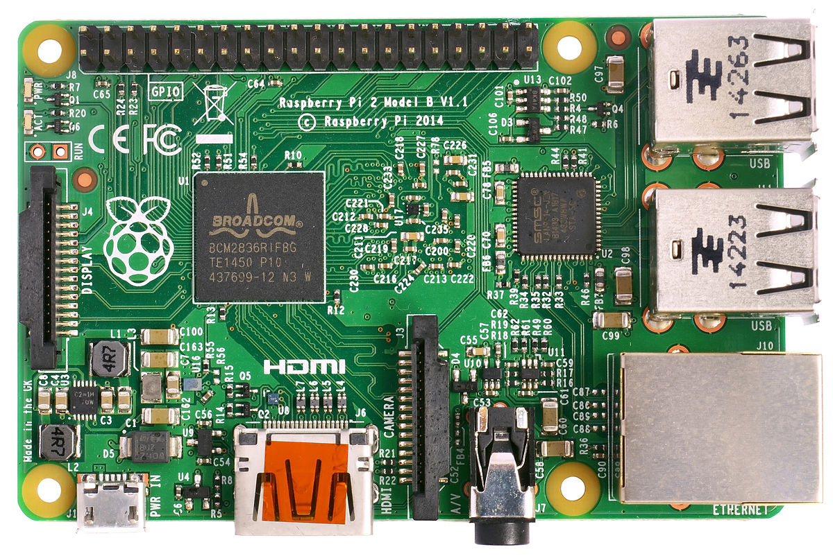
specs
Compared to the Raspberry Pi 1 it has:
- A 900MHz quad-core ARM Cortex-A7 CPU
- 1GB RAM
Like the (Pi 1) Model B+, it also has:
- 4 USB ports
- 40 GPIO pins
- Full HDMI port
- Ethernet port
- Combined 3.5mm audio jack and composite video
- Camera interface (CSI)
- Display interface (DSI)
- Micro SD card slot
- VideoCore IV 3D graphics core
https://en.wikipedia.org/wiki/Raspberry_Pi
src: https://www.raspberrypi.org/products/raspberry-pi-2-model-b/
what is cool about the Raspberry Pi:
- costs
- strong GPU that supports HD Video and 3D
- Broadcom VideoCore IV @ 250 MHz (BCM2837: 3D part of GPU @ 300 MHz, video part of GPU @ 400 MHz)[64][65]
OpenGL ES 2.0 (BCM2835, BCM2836: 24 GFLOPS / BCM2837: 28.8 GFLOPS)
MPEG-2 and VC-1 (with license),[66] 1080p30 H.264/MPEG-4 AVC high-profile decoder and encoder[24] (BCM2837: 1080p60) - this means you can run basic 3d games with sound and all:
- Broadcom VideoCore IV @ 250 MHz (BCM2837: 3D part of GPU @ 300 MHz, video part of GPU @ 400 MHz)[64][65]
what is not so cool:
- Broadcom and closed source GPU driver blobs which every privacy concerned citizen should worry about – not only Richard Stallman
- there is no open source driver for the GPU and many SmartPhones use this GPU as well, this sucks and needs to change.
- Broadcom is suspected to implement evil secret protocols into your SmartPhone’s GPS module.
- no SATA connection available so if you want to build a NAS i would recommend the ODROID or go to OpenNas.
- yes you could use 2x USB external drives to build a NAS but i am not sure if this is a reliable solution.
so i recommend it for anything that does NOT process super-sensitive data and also not inside a corporate LAN and do not hook it up to things your life depends on like nuclear reactors and stuff – or: do not hook it up to your network at all.
powersupply 240/220V:
The powersupply for Raspberry Pi 2 and higher need at least 2.000 mA (!) at 5V (for the RasPi 3 even 2.500 mA and more) (that is 10Watts or more)
you can check the voltage of the pi with a multimeter like this video shows for the old Model and the new Model B
WARNING! YOU HAVE TO HAVE A STEADY HAND OR THIS CAN DAMAGE YOUR DEVICE! (short circuit)

So you have to expect that it might NOT work on your USB-Desktop/Laptop-Port or Hub or even your USB-Phone charger might not supply as much Amps as needed and you are save to buy a Raspberry specific power supply.
So without sufficient stable power and also depending on the amount of usb connected devices the raspberry might not boot at all (the APX803 chip (which monitors voltage) triggers at 4.63±0.07V) or go into boot loop.
USB cable, they have often a high internal resistance which causes the voltage drop. (use a as short and thick as possible cable or bypass usb completely)
if the pi powers on but goes into boot loop and you watch closely you might see a text saying “undervoltage detected” accompanied with a lightning arrow on the top right corner.
dmesg|grep volt
[ 2.152246] Under-voltage detected! (0x00050005)
[ 66.632306] Under-voltage detected! (0x00050005)
i am powering my raspberry pi model B+ right now with a original or fake apple iphone/ipad adapter and it gave me 4.86 Volts, which is probably not optimal (it gives me the lightning bold every once and a while) but works pretty reliable.
If the voltage drops below 4.63v (+-5%), recent versions of the firmware will show a yellow lightning bolt symbol on the display to indicate a lack of power.


powersupply 12V/Solar+Car-Battery:
you can also power your offgrid pi by hooking it up to a 12V car battery that is charged via solar panel and charger and then use this:

as always: use short and thick USB cables over long and thin ones because voltage drops significantly the longer the cable.
software:
download the basic minimal raspbian image:
https://www.raspberrypi.org/downloads/raspbian/
up to date it is this one: http://director.downloads.raspberrypi.org/raspbian_lite/images/raspbian_lite-2018-04-19/2018-04-18-raspbian-stretch-lite.zip
350M May 6 16:30 2018-04-18-raspbian-stretch-lite.zip -unzipped-> 1.8G Apr 18 02:08 2018-04-18-raspbian-stretch-lite.img
sha256sum -c 2018-04-18-raspbian-stretch-lite.zip.sha256sum.txt
which contains:
5a0747b2bfb8c8664192831b7dc5b22847718a1cb77639a1f3db3683b242dc96 2018-04-18-raspbian-stretch-lite.zip

and says: ok
# insert microsdcard via adapter into your sdcard slot of your laptop
dmesg
# check where it is mounted
# unmount all partitions of this sdcard
umount /dev/mmcblk0*

# write the file to sdcard
dd if=/projects/Downloads/2018-04-18-raspbian-stretch-lite.img of=/dev/mmcblk0
3637248+0 records in
3637248+0 records out
1862270976 bytes (1.9 GB) copied, 858.659 s, 2.2 MB/s
login:
if you managed to power it up connected to a hdmi screen you are seeing a linux terminal login prompt:
usr: pi
pwd: raspberry
HINT: if you are using a GERMAN KEYBOARD Y = Z AND Z = Y!
CONGRATULATIONS!
you have first time successfully bootet up a raspberry! 🙂
PS: at first boot the raspberry seems to do some initialization and setup so the first boot will be slower than subsequent boots.
ssh: remote control
in order to remotely login to your LAN connected pi start the ssh service like:
@pi:
service --list-all; # shows all available services
systemctl start ssh; # start ssh service
systemctl enable ssh; # autostart ssh service

@client:
ssh pi@192.168.0.124
The authenticity of host '192.168.0.124 (192.168.0.124)' can't be established.
ECDSA key fingerprint is SHA256:Y6p1OVvowyRe9bzG51kaqgz5Sp1jM1FCHJfKZSeErIw.
ECDSA key fingerprint is MD5:5f:f0:34:a6:e9:e8:6b:f7:c1:c7:3b:dd:c4:e3:ef:42.
Are you sure you want to continue connecting (yes/no)? yes
Warning: Permanently added '192.168.0.124' (ECDSA) to the list of known hosts.
pi@192.168.0.124's password:
Linux raspberrypi 4.14.34-v7+ #1110 SMP Mon Apr 16 15:18:51 BST 2018 armv7l

The programs included with the Debian GNU/Linux system are free software;
the exact distribution terms for each program are described in the
individual files in /usr/share/doc/*/copyright.

Debian GNU/Linux comes with ABSOLUTELY NO WARRANTY, to the extent
permitted by applicable law.
Last login: Sun May  6 16:47:50 2018
pi@raspberrypi:~ $
Congratulations! You just logged in remotely! 🙂
nice commands:
pi@raspberrypi:~ $ sudo bash; # become root
root@raspberrypi:/home/pi#

htop; # see what programs are running

passwd; # change root password
passwd pi; # change password of user pi (i changed it to pi)
apt-get update; # update apt software packages cache
apt-get upgrade; # upgrade all installed software packages
all i had to update was: bluez-firmware: This firmware is required for operation of Bluetooth dongles based on the Broadcom BCM203x chipset.
apt-get install aptitude rsync htop less vim bc; # install basic software
aptitude update; # update aptitude database
# make ll work in terminal (relogin afterwards)
echo 'alias ll="ls -lah --color=auto"' >> /etc/bash.bashrc;
echo 'alias grep="grep --color"' >> /etc/bash.bashrc;
get info about hardware
output of dmesg on raspberry pi 2 model B v1.1.txt
hostnamectl; # checkout linux version and cpu type
   Static hostname: raspberrypi
         Icon name: computer
  Operating System: Raspbian GNU/Linux 9 (stretch)
            Kernel: Linux 4.14.34-v7+
      Architecture: arm

lscpu; # detailed info about CPU
Architecture:          armv7l
Byte Order:            Little Endian
CPU(s):                4
On-line CPU(s) list:   0-3
Thread(s) per core:    1
Core(s) per socket:    4
Socket(s):             1
Model:                 5
Model name:            ARMv7 Processor rev 5 (v7l)
CPU max MHz:           900.0000
CPU min MHz:           600.0000
BogoMIPS:              38.40
Flags:                 half thumb fastmult vfp edsp neon vfpv3 tls vfpv4 idiva idivt vfpd32 lpae evtstrm

lsusb; # list all usb devices
Bus 001 Device 005: ID 045e:0780 Microsoft Corp. Comfort Curve Keyboard 3000
Bus 001 Device 004: ID 7392:7811 Edimax Technology Co., Ltd EW-7811Un 802.11n Wireless Adapter [Realtek RTL8188CUS]
Bus 001 Device 003: ID 0424:ec00 Standard Microsystems Corp. SMSC9512/9514 Fast Ethernet Adapter
Bus 001 Device 002: ID 0424:9514 Standard Microsystems Corp. SMC9514 Hub
Bus 001 Device 001: ID 1d6b:0002 Linux Foundation 2.0 root hub
setup gui desktop
under linux – you are not stuck with one desktop like under windows.
no! you can choose between multiple desktops and window managers.
my favorite one is MATE based on Gnome2.
It is beautiful and basic and needs like 150MBytes of RAM all for itself.
while you could run Ubuntu MATE on your Raspberry Pi, i guess it won’t run anything smooth.
just for giggles i gonna setup MATE by myself on Debian and hope it does a little better. (Ubuntu is bloated)
and if that consumes too much ressources, i gonna start from scratch and setup lxde.
default gui: pixel (lxde based)
![]()
“Pi Improved Xwindows Environment, Lightweight”
it is probably the best performing and most optimized gui for the pi.
optional: mate on debian/raspian
# now one has to think of how to install Gnome2 MATE Desktop without OpenLibreOffice ????

apt-cache search mate|grep core; # checkout what packages are there

apt-get install mate-core; # install Gnome2 MATE
# this will download 900MByte of stuff
apt-get install lightdm;
which will also install xorg server…
reboot;
and you should have that beautiful sleek gnome2 desktop…
first impressions: it works 🙂
but as soon as you start to type in your login credentials (still usr: pi pwd: pi) it is kind of lagging, and i am not even sure what is to blame… it could be the sdcard. (you really want to get your hands on an sandisk extreme)
if you are looking for a lightweight desktop replacement, i would compare it to the ODROID (8x ARM cores@2.0Ghz, with 2GB of RAM) and then make a choice. (the ODROID costs almost 2x as much as the Pi but also definitely packs more power)
tuning mate setup:
apt-get install network-manager-gnome; # you probably want easy network management
optional: setup lxde:
apt-get install lxde-core xserver-xorg xinit
wifi dongle setup:
if despite all privacy concerns you would like the pi to connect to your LAN via wifi:
this dongle has proven to work “out of the box”: Edimax Technology Co., Ltd EW-7811Un 802.11n Wireless Adapter [Realtek RTL8188CUS]
iwlist wlan0 scan
benchmark (no turbo mode, default)
this is what the benchmark script looks like:
apt-get install sysbench;
vim /scripts/bench_cpu.sh

#!/bin/bash

NUM_CORES=$(grep -c ^processor /proc/cpuinfo)

echo "============ CPU MIPS and FLOPS"

cat /proc/cpuinfo | grep -ie hardware;
cat /proc/cpuinfo | grep -ie model;
cat /proc/cpuinfo | grep -ie mips;
cat /proc/cpuinfo | grep -ie flops;

echo "============ CPU BENCHMARK"

sysbench --test=cpu --cpu-max-prime=20000 run --num-threads=$NUM_CORES
script to monitor CPU Mhz, Voltage and Temp:
vim /scripts/sysmon.sh;
#!/bin/bash

while true ; do

	cpu_temp=$(< /sys/class/thermal/thermal_zone0/temp)
	cpu_temp=$(($cpu_temp/1000))
	echo "CPU Temp: "$cpu_temp" C"

	cpu_frq=$(< /sys/devices/system/cpu/cpu0/cpufreq/scaling_cur_freq)
	cpu_frq=$(($cpu_frq/1000))
	echo "CPU: "$cpu_frq" Mhz"

	for id in core sdram_c sdram_i sdram_p
	do
         echo -e "$id:\t$(vcgencmd measure_volts $id)"
        done

	sleep 3;
	clear;

done # executes COMMAND every second
sample output: (will refresh every 3 seconds)
CPU Temp: 52 C
CPU: 1000 Mhz
core:	volt=1.2000V
sdram_c:	volt=1.2000V
sdram_i:	volt=1.2000V
sdram_p:	volt=1.2250V
results:
============ CPU MIPS and FLOPS
Hardware	: BCM2835
model name	: ARMv7 Processor rev 5 (v7l)
model name	: ARMv7 Processor rev 5 (v7l)
model name	: ARMv7 Processor rev 5 (v7l)
model name	: ARMv7 Processor rev 5 (v7l)
BogoMIPS	: 38.40
BogoMIPS	: 38.40
BogoMIPS	: 38.40
BogoMIPS	: 38.40
============ CPU BENCHMARK
sysbench 0.4.12:  multi-threaded system evaluation benchmark

Running the test with following options:
Number of threads: 4

Doing CPU performance benchmark

Threads started!
Done.

Maximum prime number checked in CPU test: 20000


Test execution summary:
    total time:                          145.9523s
    total number of events:              10000
    total time taken by event execution: 583.6457
    per-request statistics:
         min:                                 57.51ms
         avg:                                 58.36ms
         max:                                 83.79ms
         approx.  95 percentile:              61.14ms

Threads fairness:
    events (avg/stddev):           2500.0000/19.89
    execution time (avg/stddev):   145.9114/0.02
the temperature rises from 41 degrees celsius to 55 degrees celsius and stays there (no active heating)
total time: 145.9523s
to comparison: with passive cooling the odroid finished the same benchmark in:
total time: 37.4554s
which makes the odroid 4x times faster than the raspberry pi 2 model B v1.1
benchmark: basic overclocking
this will NOT void the warranty, because it is not using the turbo_mode (steady high Mhz)
max temp for raspberry pi is 85 degree celsius.
force_turbo mode
force_turbo=0
enables dynamic clocks and voltage for the ARM core, GPU core and SDRAM. When busy, ARM frequency go up to “arm_freq” and down to “arm_freq_min” on idle. “core_freq”, “sdram_freq” and “over_voltage” behave the same. “over_voltage” is limited to 6 (1.35 V). Non default values for the H.264/V3D/ISP parts are ignored.
force_turbo=1
disables dynamic clocking, so all frequencies and voltages stay high. Overclocking of H.264/V3D/ISP GPU parts is allowed as well as setting “over_voltage” to 8 (1.4 V). [8]
dynamic clocking means: the voltage and frequency of CPU, RAM and GPU are adjusted to workload.
If there is high workload it will go to the maximum specified, if there is low workload it will throttle down.
vcgencmd get_config int|grep freq
arm_freq=900
sdram_freq=450

get_config int|grep turbo
disable_auto_turbo=1
basic overclocking: +4.5% more speed
those values have worked for me: (src)
will set CPU to 1000Mhz max (under load)
echo '
arm_freq=1000
sdram_freq=500
core_freq=500
over_voltage=2
' >> /boot/config.txt;

reboot;
after reboot if you rerun this command: you will realize it accepted the new settings and RAM are +50Mhz and CPU +100Mhz:
vcgencmd get_config int|grep freq
arm_freq=1000
core_freq=500
sdram_freq=500
results: CPU heats up to 62 degrees celsius
/scripts/bench_cpu.sh
============ CPU MIPS and FLOPS
Hardware	: BCM2835
model name	: ARMv7 Processor rev 5 (v7l)
model name	: ARMv7 Processor rev 5 (v7l)
model name	: ARMv7 Processor rev 5 (v7l)
model name	: ARMv7 Processor rev 5 (v7l)
BogoMIPS	: 38.40
BogoMIPS	: 38.40
BogoMIPS	: 38.40
BogoMIPS	: 38.40
============ CPU BENCHMARK
sysbench 0.4.12:  multi-threaded system evaluation benchmark

Running the test with following options:
Number of threads: 4

Doing CPU performance benchmark

Threads started!
Done.

Maximum prime number checked in CPU test: 20000


Test execution summary:
    total time:                          139.4115s
    total number of events:              10000
    total time taken by event execution: 557.5274
    per-request statistics:
         min:                                 51.76ms
         avg:                                 55.75ms
         max:                                113.60ms
         approx.  95 percentile:              87.19ms

Threads fairness:
    events (avg/stddev):           2500.0000/12.81
    execution time (avg/stddev):   139.3818/0.02
so this gave a +4.5% in overall performance, as you can calculate with bc the terminal calculator=
scale=5
(145.9523-139.4115)/(145.9523/100) = 4.48147
https://www.raspberrypi.org/blog/introducing-turbo-mode-up-to-50-more-performance-for-free/
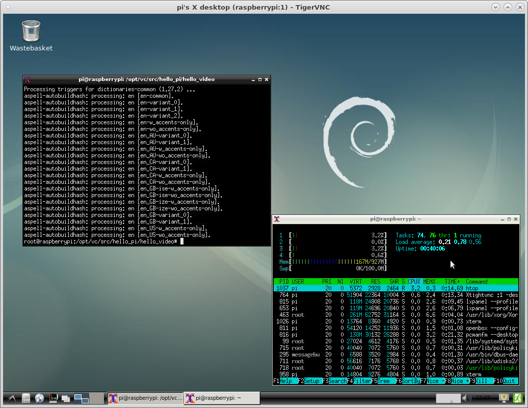
vnc
can give some headaches…. but you can do it! 🙂
display:0
display:0 is the same as monitor output, x11vnc can do that (so you will see the same inside vnc window as on your monitor)
… if you want separate screens (display:0 = monitor, display:1 = remote vnc output) scroll down to tightvncserver.
disadvantage: if your HDMI connected monitor has a very high resolution, the raspberry Pi B+ will use up 20-30% of CPU power just to transmit the VNC screen.
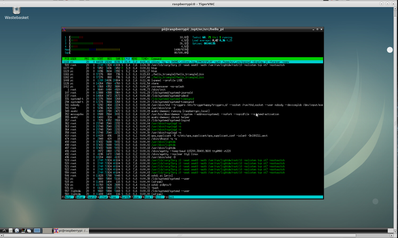
apt-get install x11vnc; # install x11vnc
x11vnc -storepasswd; # generate a per user password file
Enter VNC password:
Verify password:
Write password to /home/pi/.vnc/passwd? [y]/n y
Password written to: /home/pi/.vnc/passwd
x11vnc -display :0 -auth .Xauthority -rfbauth /home/pi/.vnc/passwd -forever;
# start the vnc x11 server on display 0
# if one is using MATE Gnome2, one can place the line above into autostart applications
# if the program quits / stops... something is wrong and you need to scroll up to see the error message like:
###############################################################
#@@@@@@@@@@@@@@@@@@@@@@@@@@@@@@@@@@@@@@@@@@@@@@@@@@@@@@@@@@@@@#
#@ @#
#@ ** WARNING ** WARNING ** WARNING ** WARNING ** @#
#@ @#
#@ YOU ARE RUNNING X11VNC WITHOUT A PASSWORD!! @#
#@ @#
#@ This means anyone with network access to this computer @#
#@ may be able to view and control your desktop. @#
#@ @#
#@ >>> If you did not mean to do this Press CTRL-C now!! <<< @#
#@ @#
#@@@@@@@@@@@@@@@@@@@@@@@@@@@@@@@@@@@@@@@@@@@@@@@@@@@@@@@@@@@@@#
#@ @#
#@ You can create an x11vnc password file by running: @#
#@ @#
#@ x11vnc -storepasswd password /path/to/passfile @#
#@ or x11vnc -storepasswd /path/to/passfile @#
#@ or x11vnc -storepasswd @#
#@ @#

# if you are confident things work you can run it in background like this, without the verbose output
x11vnc -bg -o %HOME/.x11vnc.log.%VNCDISPLAY -auth /home/pi/.vnc/passwd -display :0 -forever -nopw

# and connect
/usr/bin/vncviewer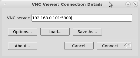
display:1
tightvnc is pretty cool and easy to setup as well:
sudo apt-get install tightvncserver; # install server
# become non-root standard user
tightvncserver; # configure a password and start the service/vnc-server
netstat -lptun|grep vnc; # check if vncserver is running and what ports are used
tcp 0 0 0.0.0.0:5901 0.0.0.0:* LISTEN 764/Xtightvnc
tcp 0 0 0.0.0.0:6001 0.0.0.0:* LISTEN 764/Xtightvnc
now on a different machine fireup your default vnc viewer (tight vnc is really cool).
# centos tigervnc
yum list installed|grep vnc
tigervnc.x86_64                       1.8.0-2.el7_4                    @updates

/usr/bin/vncviewer
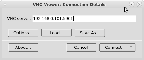
if it says “connection refused” check if you have entered the correct ip-address / port and firewall allows TCP connections to port 5901:
iptables -A INPUT -m state --state NEW -m tcp -p tcp --dport 5901 -j ACCEPT
iptables -A INPUT -m state --state NEW -m tcp -p tcp --dport 6001 -j ACCEPT
systemctl restart iptables
security
https://www.raspberrypi.org/documentation/configuration/security.md
install a basic firewall:
apt-get install gufw ufw; # install gufw and gufw gui
apt-get install firewall-config firewalld; # install firewalld and gui

# ufw is pretty easy in handling
ufw enable; # enable autostart firewall service
ufw disable; # disable firewall
ufw allow 22; # allow port 22
ufw deny 22; # deny port 22
ufw allow 22/tcp; # same same
ufw allow 5901/tcp; # allow vnc
ufw allow ssh; # same same
ufw status; # status info
Status: active

To                         Action      From
--                         ------      ----
22/tcp                     ALLOW       Anywhere
5901/tcp                   ALLOW       Anywhere
22/tcp (v6)                ALLOW       Anywhere (v6)
5901/tcp (v6)              ALLOW       Anywhere (v6)
programming coding the pi: hello world
the “default” programming language to interact with the pi seems to be python. hence the name? 😉
but you could (of course) use any other like C, Bash, PHP/PERL (needs to be installed first) or Java.
c – hello world
there are some demos under this folder:
pi@raspberrypi:/opt/vc/src/hello_pi $ ll
total 84K
drwxrwxr-x 17 pi   pi   4.0K Apr 18 00:20 .
drwxr-xr-x  3 root root 4.0K Apr 18 00:20 ..
drwxrwxr-x  2 pi   pi   4.0K May  7 10:53 hello_audio
drwxrwxr-x  2 pi   pi   4.0K May  7 10:53 hello_dispmanx
drwxrwxr-x  2 pi   pi   4.0K May  7 10:53 hello_encode
drwxrwxr-x  4 pi   pi   4.0K May  7 10:53 hello_fft
drwxrwxr-x  2 pi   pi   4.0K May  7 10:53 hello_font
drwxrwxr-x  2 pi   pi   4.0K May  7 10:53 hello_jpeg
drwxrwxr-x  2 pi   pi   4.0K May  7 10:53 hello_mmal_encode
drwxrwxr-x  2 pi   pi   4.0K May  7 10:53 hello_teapot
drwxrwxr-x  2 pi   pi   4.0K May  7 10:53 hello_tiger
drwxrwxr-x  2 pi   pi   4.0K May  7 10:52 hello_triangle
drwxrwxr-x  2 pi   pi   4.0K May  7 10:52 hello_triangle2
drwxrwxr-x  2 pi   pi   4.0K May  7 10:52 hello_video
drwxrwxr-x  2 pi   pi   4.0K May  7 10:53 hello_videocube
drwxrwxr-x  2 pi   pi   4.0K May  7 10:52 hello_world
drwxrwxr-x  4 pi   pi   4.0K Apr 18 00:20 libs
-rw-rw-r--  1 pi   pi   1.1K Mar 28 12:07 Makefile
-rw-rw-r--  1 pi   pi   1.3K Feb  9 17:48 Makefile.include
-rw-rw-r--  1 pi   pi    526 Feb  9 17:48 README
-rwxrwxr-x  1 pi   pi     27 Mar 28 12:07 rebuild.sh

# if those files are missing for some reason here is the download mirror:
wget --no-check-certificate https://dwaves.de/projects/raspberrypi/hello_pi.tar.gz
# run to rebuild all demos and meassure how long this takes (overclocked to 1GHz)
time ./rebuild.sh
real	0m38.526s

# the c hello world reads like

cat ./hello_world/world.c
/*
Copyright (c) 2012, Broadcom Europe Ltd
All rights reserved.

Redistribution and use in source and binary forms, with or without
modification, are permitted provided that the following conditions are met:
    * Redistributions of source code must retain the above copyright
      notice, this list of conditions and the following disclaimer.
    * Redistributions in binary form must reproduce the above copyright
      notice, this list of conditions and the following disclaimer in the
      documentation and/or other materials provided with the distribution.
    * Neither the name of the copyright holder nor the
      names of its contributors may be used to endorse or promote products
      derived from this software without specific prior written permission.

THIS SOFTWARE IS PROVIDED BY THE COPYRIGHT HOLDERS AND CONTRIBUTORS "AS IS" AND
ANY EXPRESS OR IMPLIED WARRANTIES, INCLUDING, BUT NOT LIMITED TO, THE IMPLIED
WARRANTIES OF MERCHANTABILITY AND FITNESS FOR A PARTICULAR PURPOSE ARE
DISCLAIMED. IN NO EVENT SHALL THE COPYRIGHT HOLDER OR CONTRIBUTORS BE LIABLE FOR ANY
DIRECT, INDIRECT, INCIDENTAL, SPECIAL, EXEMPLARY, OR CONSEQUENTIAL DAMAGES
(INCLUDING, BUT NOT LIMITED TO, PROCUREMENT OF SUBSTITUTE GOODS OR SERVICES;
LOSS OF USE, DATA, OR PROFITS; OR BUSINESS INTERRUPTION) HOWEVER CAUSED AND
ON ANY THEORY OF LIABILITY, WHETHER IN CONTRACT, STRICT LIABILITY, OR TORT
(INCLUDING NEGLIGENCE OR OTHERWISE) ARISING IN ANY WAY OUT OF THE USE OF THIS
SOFTWARE, EVEN IF ADVISED OF THE POSSIBILITY OF SUCH DAMAGE.
*/

// Classic Hello World

#include

int main(void)
{
   printf("Hello world!\n");
   return 0;
}


# run it
./hello_world/hello_world.bin
Hello world!

# CELEBRATE! pour yourself one more coffee and keep going...
for me it is pretty important to have some proper IDE that can do step debugging inside it (or a separate GUI tool that can do that… but integrated into IDE would be nice just like with Java and Eclipse)
very basic terminal debugging c: https://www.thegeekstuff.com/2010/03/debug-c-program-using-gdb/
https://www.tecmint.com/best-linux-ide-editors-source-code-editors/
more convenient:
http://xmodulo.com/debug-program-nemiver-debugger.html
python
you could write python on a different machine and then load it to the pi, or simply install an ide directly on the pi and code and run directly on the pi:
apt-cache search Thonny
python3-thonny - Python IDE for beginners
apt-get install python3-thonny
https://projects.raspberrypi.org/en/projects/demo-programs
messing / controlling gpio / relays / servos
this is where the general purpose input / output pins (GPIO) come in handy.


bash:
yeah! you can control the GPIO pins by bash! great!
i packed this in a bunch of scripts: 1. init 2. on 3. off 4. loop: that you can download here: bash_pin18_gpio_on_off_scripts.tar.gz
# Enable GPIO 18 access via the Kernel on path /sys/class/gpio/
echo "18" > /sys/class/gpio/export;
# configure it as an output pin
echo "out" > /sys/class/gpio/gpio18/direction;

# read current state of pin18
cat /sys/class/gpio/gpio18/value;
0

# switch "on" pin18
echo "1" > /sys/class/gpio/gpio18/value;
cat /sys/class/gpio/gpio18/value;
1
# switch "off" pin18
echo "0" > /sys/class/gpio/gpio18/value;
excellent 🙂
python:
with this python script:
you can “flip a digital switch” and switch on a +3.3V current flowing between GND (Ground) and Pin18:
vim swith_on_and_off_pin18.py; # create script file

import RPi.GPIO as GPIO
import time
GPIO.setmode(GPIO.BCM)
GPIO.setwarnings(False)
GPIO.setup(18,GPIO.OUT)
print "LED on"
GPIO.output(18,GPIO.HIGH)
time.sleep(1)
print "LED off"
GPIO.output(18,GPIO.LOW)

# run it in endless loop (on, off, on, off... so you can meassure)
while true; do python gpio.py; sleep 3; clear; done;
as written here: you could hook up a led to those two ports (GND + Pin18) but only with a 330Ohm resistor in between! (or it might blow the pi)
so what do you want to switch on and off?
if you want to switch 12-24Volts this relays card can work:

8x 12V relay card wirering GPIO schematics pinout raspberry pi2 Model B v1.1:
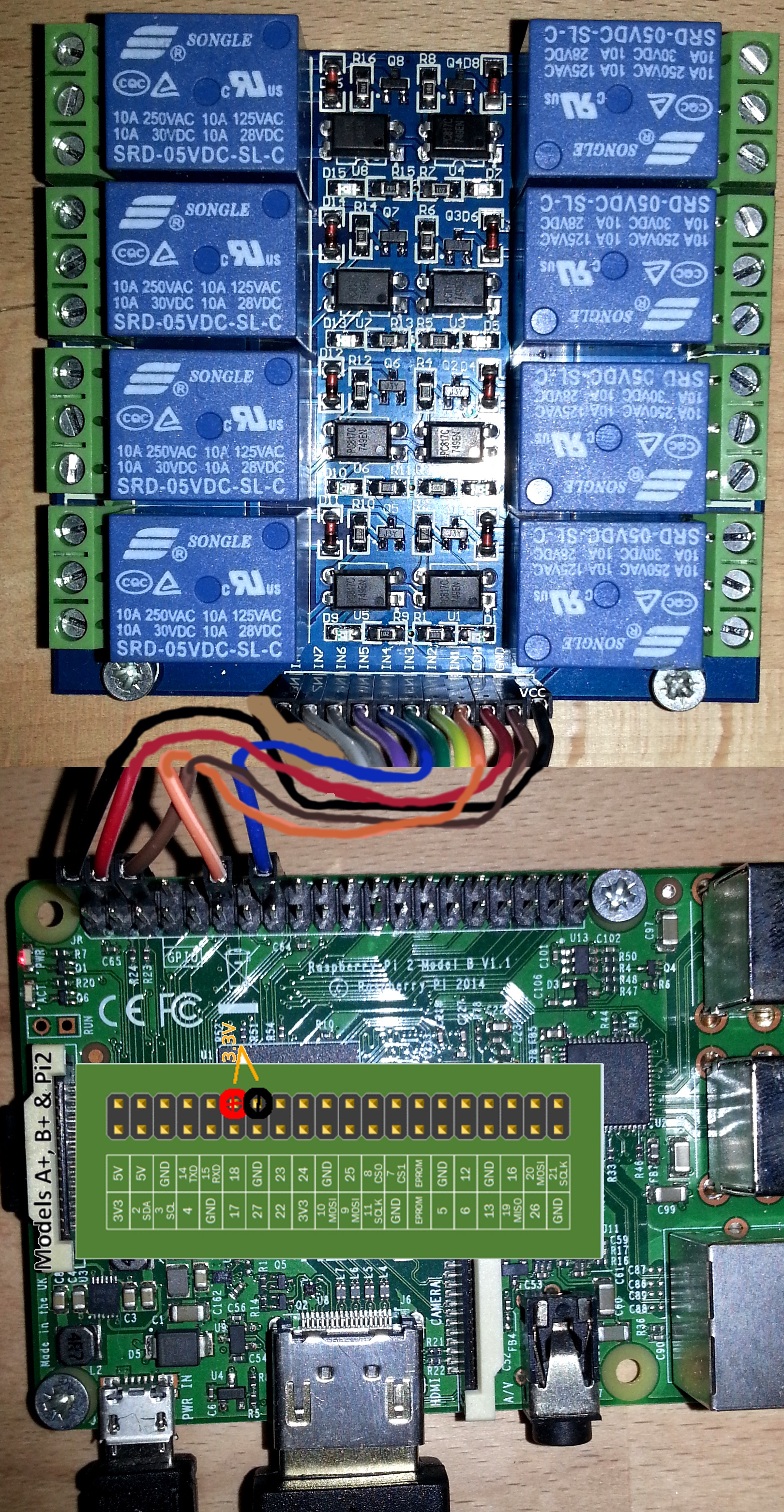
i am not sure if this is the correct way to do it – or if i have to put 470Ohms between the GPIOs and the relay card, but it works! 🙂
in the above schematics only two relays are connected:
-
Relay1 is orange-wired to GPIO 18
-
Relay4 is blue -wired to GPIO 23
with this bash script you can make them switch on an off:
note: pin_on used to be pin_init, but it seems during “init” the pin is turned on.
also note: this project is for water irigation, i want the relay to switch on (pump starts) for 10min a day.
also when the power fails on the raspberry the relay should automatically switch off (pump off).
so strange enough in contrast to the last bash relay control commands, echo 0 > gpio actually switches the pin/relay on!
X-D (LED on, relay on, circuit is closed, water pump starts).
don’t get confused!
mkdir -p /projects/bash/
cd /projects/bash/
vim pin_on.sh
#!/bin/bash
# Enable GPIO $1 access via the Kernel on path /sys/class/gpio/
echo $(date '+DATE: %Y-%m-%d TIME: %H:%M:%S')" pin $1 on" | tee -a /var/log/gpio_$(date '+%Y-%m').log
echo "$1" > /sys/class/gpio/export;
# configure it as an output pin
echo "out" > /sys/class/gpio/gpio$1/direction;

# pin goes on state without this
# echo 0 > /sys/class/gpio/gpio$1/value;
vim pin_off.sh
#!/bin/bash
echo $(date '+DATE: %Y-%m-%d TIME: %H:%M:%S')" pin $1 off" | tee -a /var/log/gpio_$(date '+%Y-%m').log

# switch "off" pin$1
echo "1" > /sys/class/gpio/gpio$1/value;
vim pin_on_off_loop.sh
#!/bin/bash
while true; do

echo "pin "$1" off";
/projects/bash/pin_off.sh $1;
cat /sys/class/gpio/gpio$1/value;

sleep 1;

echo "pin "$1" on";
/projects/bash/pin_on.sh $1
cat /sys/class/gpio/gpio$1/value;

sleep 1;

done;
now you should be able to switch relay1 and relay4 like this:
/projects/bash/pin_on.sh 18
/projects/bash/pin_off.sh 18
as well as continous on off loop:
/projects/bash/on_off_loop.sh 18
you might realize there is also a logging line in the script, that writes a log file to /var/log/gpio_20YY-MM.log
if you don’t like that just #comment it out.
also checkout those relay related links:
https://www.raspberrypi.org/forums/viewtopic.php?f=44&t=216304

datasheet of the card (in German): https://www.pollin.de/productdownloads/D810273B.PDF
datasheet of the relay SRD-05VDC-SL-C: http://www.circuitbasics.com/wp-content/uploads/2015/11/SRD-05VDC-SL-C-Datasheet.pdf
mirror: SRD-05VDC-SL-C-Datasheet.pdf
cron job
in order to make it a timed switching on and off, linux uses cronjobs.
su; # become root
crontab -e; # create and edit crontab

# m   h  dom mon dow   command
  01  1  *   *   *     /projects/bash/pin_on.sh 18
  02  1  *   *   *     /projects/bash/pin_off.sh 18
this will call the on script at 01:01 oclock, and the off script one minute later (testing) 01:02 oclock.
i can verify it works, by following the log file:
tail -f /var/log/gpio_2018-06.log

DATE: 2018-06-29 TIME: 01:01:01 pin 18 on
DATE: 2018-06-29 TIME: 01:02:01 pin 18 off
okay you could say it is 1 second “too late”.
does not matter to me right now.
Real Time Clock: RTC


just as the Raspberry pi, the odroid needs a battery to keep clock when it is turned off.
https://www.sigmdel.ca/michel/ha/rpi/rtc_en.html
https://www.hardkernel.com/main/products/prdt_info.php?g_code=G137508214939
- power off raspberry (init 0; as root will do the job) , disconnect from power, install rtc module as shown in above pictures.
-
# set correct timezone
# show currently set timezone
timedatectl;
# list all available timezones: (works Centos7, Debian8, Suse12)
timedatectl list-timezones;
# set it
timedatectl set-timezone America/Chicago;
- put the below line into the vim /boot/config.txt file: (edit it with your favourite editor and type the line in – or copy and paste it from here
 )
)
dtoverlay=i2c-rtc,ds3231 - edit the vim /lib/udev/hwclock-set file (sudo nano /lib/udev/hwclock-set) and “comment out” the following lines (“comment out” means put a # at the beginning of each of the lines, so they become comments and are ignored by the system)if [ -e /run/systemd/system ] ; then
exit 0
fiso they become:#if [ -e /run/systemd/system ] ; then
# exit 0
#fi - get time from timeserver
apt-get install ntp; # install ntp
ntpdate de.pool.ntp.org; # get time from this timeserver
28 Jun 23:25:48 ntpdate[17972]: adjust time server 62.128.1.18 offset -0.009922 sec
hwclock --systohc; # write system time to rtc clock (save the time you got from the internet)
- have some fun with time
-
alias datum="date '+DATE: %Y-%m-%d TIME: %H:%M:%S'";
alias loopdatum="while true ; do datum ; sleep 1 ; clear; done";
loopdatum; # will display real time clock in terminal
read time directly from rtc module
hwclock -rupdate rtc module time from system time (system time should be regularly updated by ntp from the internet if your pi is networked):
hwclock -wupdate system time from the rtc module (this should happen on startup):
hwclock -sand the most fun of all – monitor the “drift” between your system clock and the rtc module:
hwclock -csrc: https://www.raspberrypi.org/forums/viewtopic.php?t=161133
- testing: test by powering off the pi, disconnecting network cable (if you’re running wireless, you may need to turn your router off for a bit), plug a screen into the hdmi output of the pi, wait 10 mins, then power it up. Once it’s up, using a locally connected keyboard, log in and type “date” – if the time is correct and not 10 mins slow (or however long you had the pi powered down for) then the system has read the time correctly from the rtc module!!
-
funky fact about the rtc: it has a temp sensor
you can read the temp sensor of this rtc with python like this:
import smbus
import os

bus = smbus.SMBus(1)
address = 0x68

os.system('sudo rmmod rtc_ds1307')
def getTemp(address):
   byte_tmsb = bus.read_byte_data(address,0x11)
   byte_tlsb = bin(bus.read_byte_data(address,0x12))[2:].zfill(8)
   return byte_tmsb+int(byte_tlsb[0])*2**(-1)+int(byte_tlsb[1])*2**(-2)

#print getTemp(address)
Celsius = getTemp(address)
Fahrenheit = 9.0/5.0 * Celsius + 32
print Fahrenheit, "*F /", Celsius, "*C"
os.system('sudo modprobe rtc_ds1307')
than call the script like this:
python ./temp_from_rtc.py
samle output: well this is definately NOT my room temperature X-D
86.45 *F / 30.25 *C
you can try to get more real world values like this:
Celsius = getTemp(address)
Celsius = Celsius - 10;
liked this article?
- only together we can create a truly free world
- plz support dwaves to keep it up & running!
- (yes the info on the internet is (mostly) free but beer is still not free (still have to work on that))
- really really hate advertisement
- contribute: whenever a solution was found, blog about it for others to find!
- talk about, recommend & link to this blog and articles
- thanks to all who contribute!